
Hello. I will explain how to measure and decide lumped elements values for WPT coil.
Here is the WPT coil that I made for my experiments. The WPT coil consists of a resonant coil and a feed coil with SMA connector. The resonant coil is spiral and has parasitic capacitance between the spiral lines and this capacitance make this coil resonate at LC resonant frequency. The feed coil is a simple circular shape that is connected with SMA connector. Two coils are coupled with each other and the degree of coupling is expressed with mutual inductance M or coupling coefficient k.

The equivalent circuit of this coil can be shown as the following figure. Rs shows the series impedance of the signal generator system and the typical value is 50 ohm. Each coil has its own self inductance L1, L2 and parasitic capacitance C1, C2 and resistance R1 and R2. M shows the mutual inductance between the feed and the resonant coil. The coupling coefficient k is defined as the following equation. [1]
k= M/sqrt(L1*L2)

Before we start to discuss the WPT coil, I would like to explain the simple two-port network system. Let us assume that we know the each S, Z, Y and ABCD parameters of this system. and we know that each component of Z matrix.

and we will convert this known two port network system into T-shaped system. In this case, each Z parameter of this T-shaped system can be expressed by the following figure. ZL is the load impedance and we assume that R2 (Resistance of the resonant coil) is the load impedance ZL.

By using this assumption, We can calculate the ABCD matrix like the following equation.

And the input impedance of this system can be expressed with the following equation. [2]

Now we are ready to analyze the WPT coil. The equivalent circuit of the WPT coil can be replaced by the following figure.[3]

Then, each Z parameter of this WPT system is expressed like these equation. Load impedance ZL is R2 in this system.
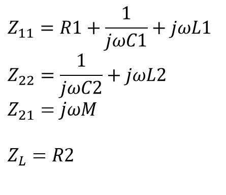
The input impedance of this WPT coil is calculated using the equation that we extracted with T shaped system.

Now we measure the S parameter of the WPT coil with a vector network analyzer.

By using the input impedance equation that we have made and optimizer tool of the VNWA, we can extract the optimized value of each lumped parameters.
Before we optimize the parameter, we can use FEM simulator to know the initial values of each parameter. We can easily calculate the self inductance and mutual inductance values with FEM. and C2 (Capacitance of the resonant coil) can be calculated by using the resonant frequency and L2 value. [4]
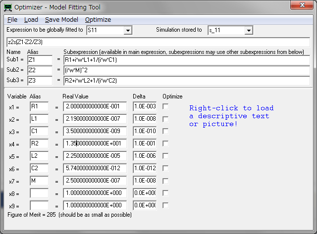
The extracted lumped elements values for WPT coil is shown at following table.
| Parameters | Value | Unit |
| R1 | 0.2 | [Ohm] |
| L1 | 2.19 | [uH] |
| C1 | 3.5 | [nF] |
| R2 | 13.5 | [Ohm] |
| L2 | 22.5 | [uH] |
| C2 | 5.74 | [pF] |
| M | 0.25 | [uH] |
To check the feasibility of the extracted lumped value, I plotted the measured and simulated values.
and Those values matches very well each other.
(1) S11 [dB]

(2) S11 [Smith Chart]

(3) Abs( Z in )

I think that our extracted values are enough to proceed the further study.
Now, we have the equivalent circuit and the extracted values of components of this WPT coil.
The we make a spice model of the WPT coil. the k is 0.11 (0.11 = M/sqrt(L1*L2)). [5]
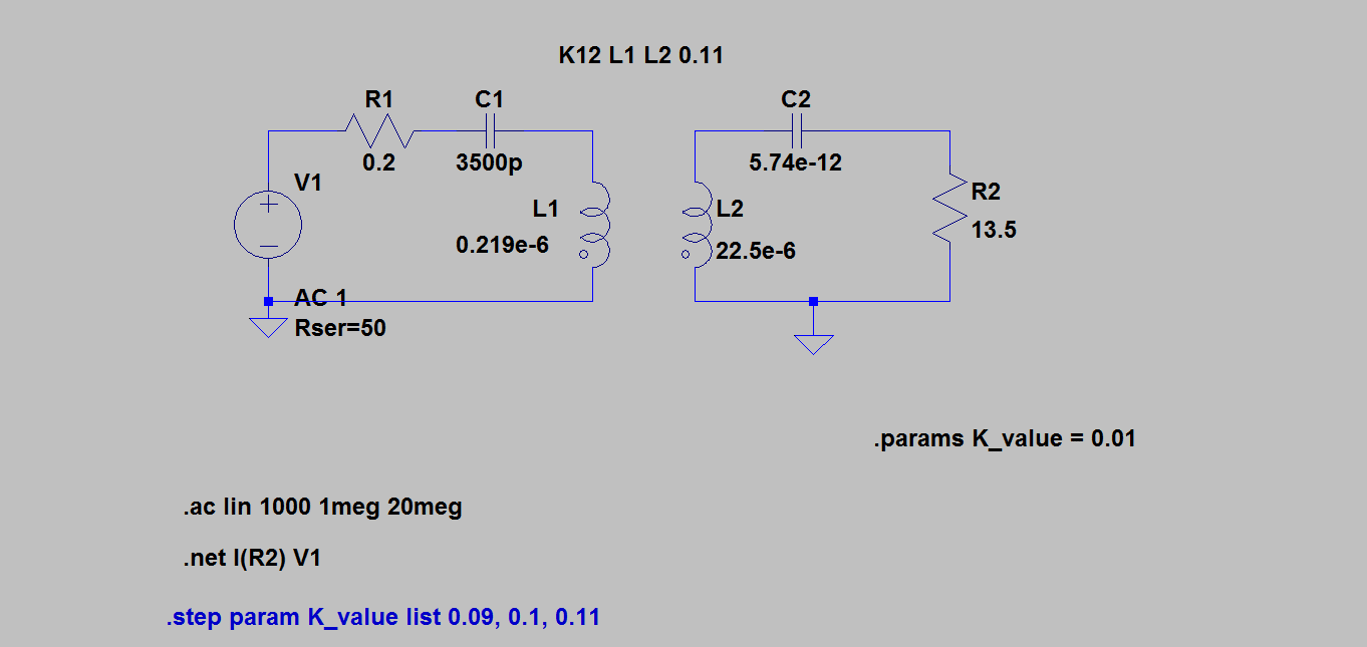
(1) Calculated S11 [dB] with spice model.

(2) Calculated Abs(Zin) [Ohm] with spice model.

Spice model also shows good agreement with the measured data.
Now, we are ready to expand this model into whole WPT system.
Thanks.
Reference
[1] Sample, A. P., Meyer, D. a., & Smith, J. R. (2011). Analysis, experimental results, and range adaptation of magnetically coupled resonators for wireless power transfer. IEEE Transactions on Industrial Electronics, 58(c), 544–554. http://doi.org/10.1109/TIE.2010.2046002
[2] Seo, D., Lee, J., & Lee, H. S. (2016). Study on Two-Coil and Four-Coil Wireless Power Transfer Systems Using Z-Parameter Approach. https://etrij.etri.re.kr/etrij/journal/article/article.do?volume=38&issue=3&page=568
[3] https://wireless-square.com/2016/11/04/z-parameters-of-the-coupled-inductors-network/
[4] https://wireless-square.com/2016/11/10/extraction-of-lumped-elements-parameters-using-vnwa/
[5] https://wireless-square.com/2016/11/02/wireless-power-transfer-analysis-using-ltspice/


[…] [1] http://wireless-square.com/2016/11/16/measuring-lumped-elements-values-for-wpt-coil/ […]